
 EN
EN
 ar
ar bg
bg hr
hr cs
cs da
da nl
nl fi
fi fr
fr de
de el
el hi
hi it
it ko
ko no
no pl
pl pt
pt ro
ro ru
ru es
es sv
sv tl
tl iw
iw id
id lv
lv lt
lt sr
sr sk
sk sl
sl uk
uk vi
vi et
et hu
hu th
th tr
tr fa
fa ms
ms hy
hy ka
ka ur
ur bn
bn mn
mn ta
ta kk
kk uz
uz ku
ku
Real-Time Dam Safety Alerts with Differential Pressure Water Level Sensors
Key Takeaways An alert chain needs more than a sensor: define field in...

Strain Gauge Load Cell Wiring That Actually Works
Load cell wiring not going as planned? Many field problems come down to a few basic mistakes: loose terminals, moisture in the junction box, or mixing up the sense and excitation lines. Even with the right instrument, a bad connection can turn good data into garbage. Over the years, we have seen enough wiring faults to know where the pain points usually are. This guide walks through the essentials — what to check first, how to handle shielded cables, and why that extra pair of sense wires matters. It is not about fancy engineering terms; it is about getting a reading you can trust on site.
Technical Detail
Most strain gauge load cells used in geotechnical and industrial weighing follow a simple color code, but never trust the label blindly. Always ring out the wires with a multimeter before connecting anything. Typical bridge resistance between EXC+ and EXC- falls in the 350Ω to 700Ω range; the signal pair shows roughly the same. A zero reading or short means trouble. When you wire in the field, keep the excitation voltage within the range specified on the datasheet — pushing it for more signal usually adds noise instead. Shield drain wires should connect to ground at one end only, preferably at the instrument side, to avoid ground loops that masquerade as signal drift. If your cable runs longer than 20 meters, the six-wire connection becomes a real advantage: the extra sense leads allow the amplifier to compensate for voltage drop along the cable, which is often overlooked. Junction boxes need desiccant packs if the environment is damp; we have seen condensation wreak havoc inside sealed enclosures. Kingmach supplies load cells with clear documentation and standard wiring, and can provide custom pinouts for OEM integrations when needed. Our technical team often helps customers troubleshoot erratic readings remotely, and the fix is frequently just a tighten of a terminal screw or re-doing a splice. For large monitoring projects, a little extra care during wiring can save hours of chasing ghosts later.
News
Key Takeaways An alert chain needs more than a sensor: define field in...
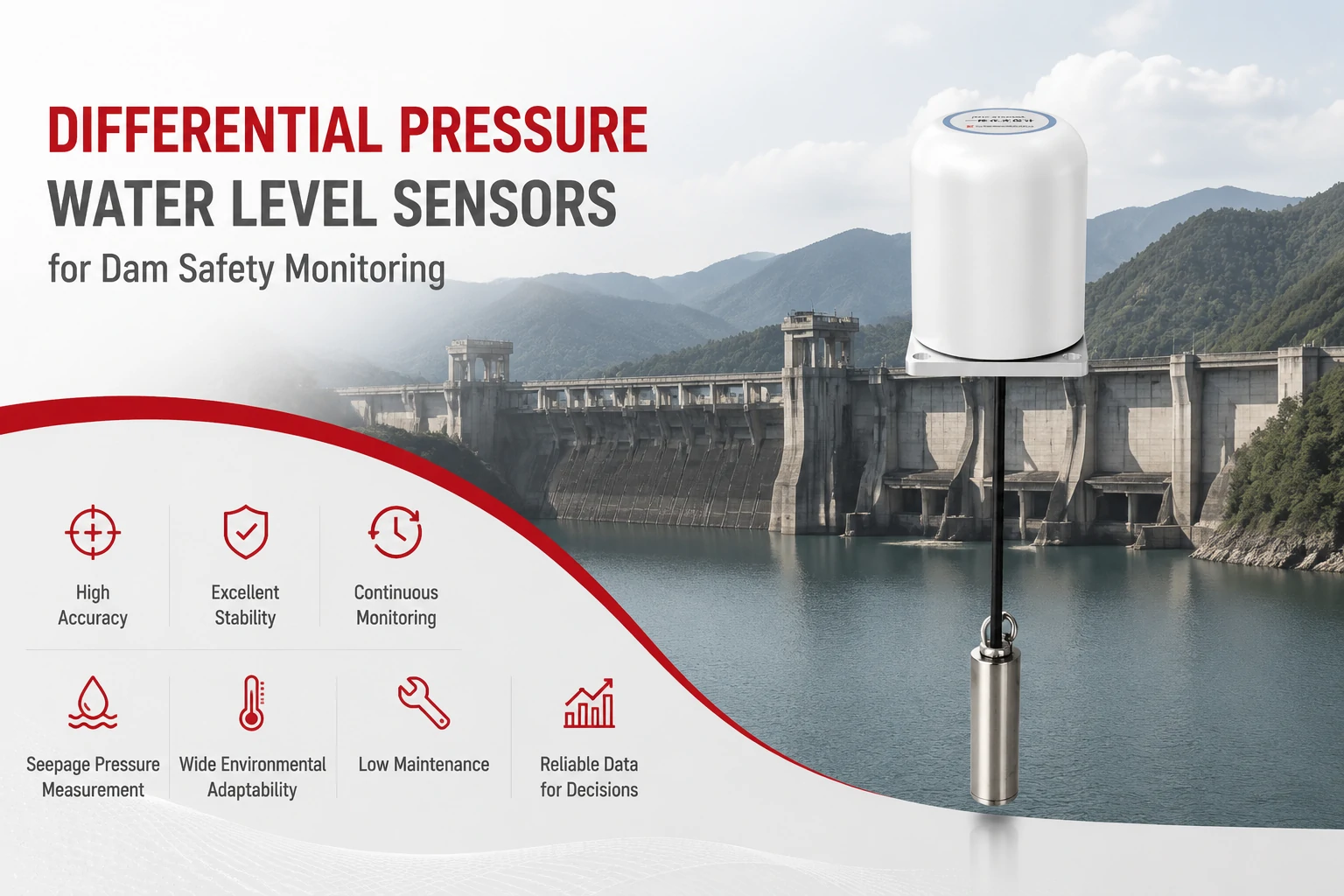
Key Takeaways The strongest fit is usually a confined, submerged, or s...
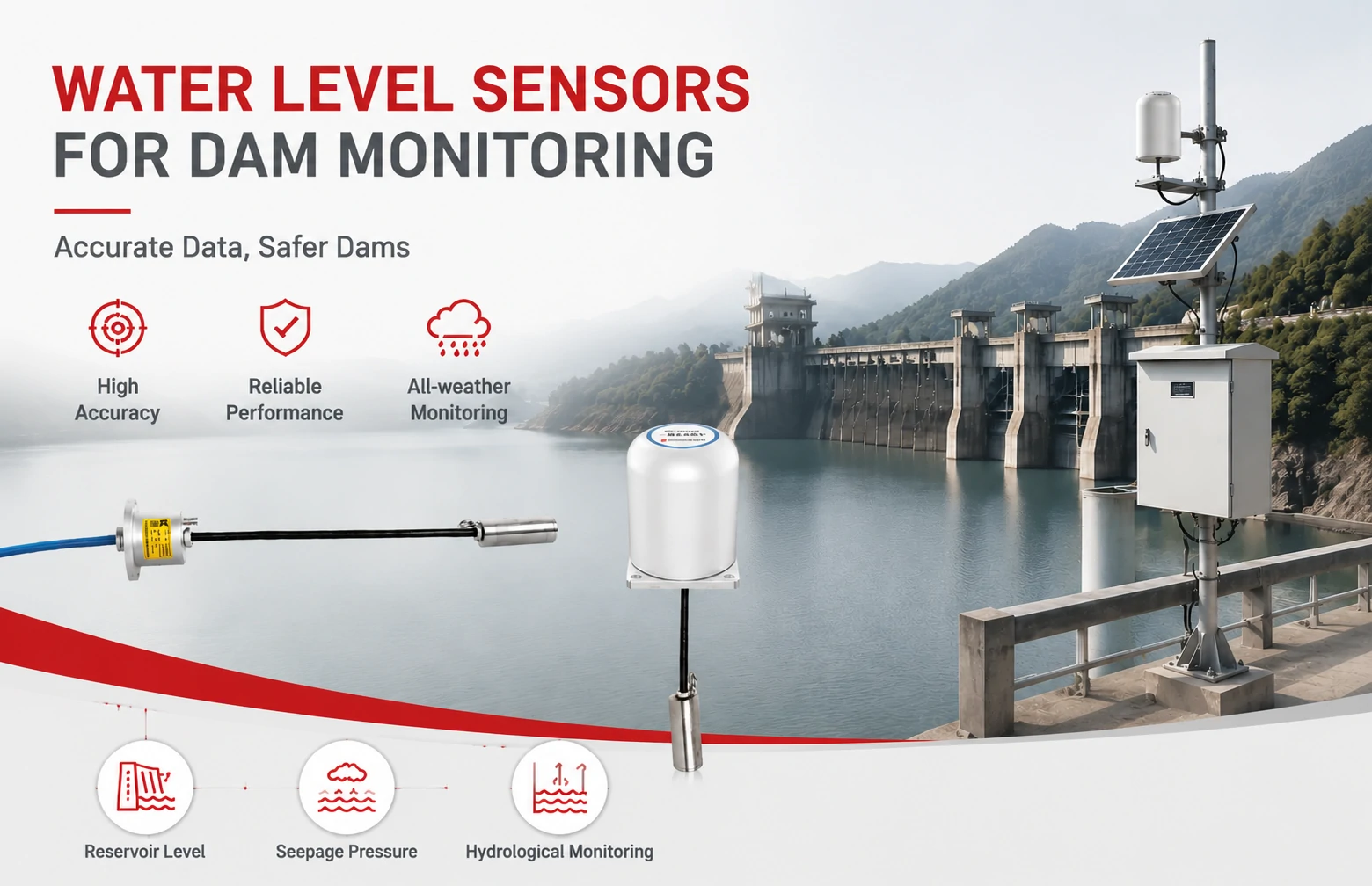
Kingmach Water Level Sensors for Dam Monitoring: A Buyer's Guide to Differential Pre...
Products
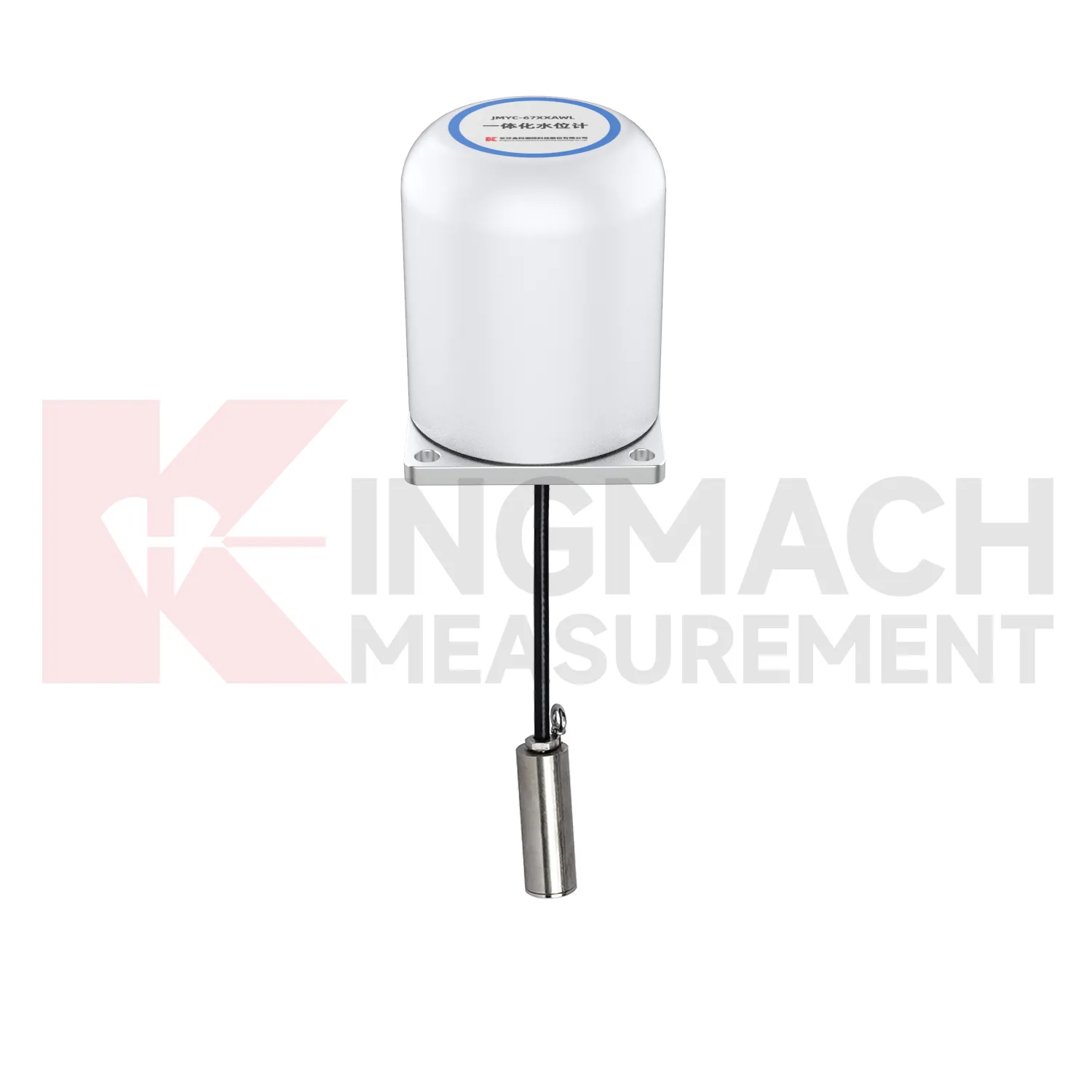
Integrated Wide-Range Differential Pressure Water Level Meter JMYC-67XXAWL
View Details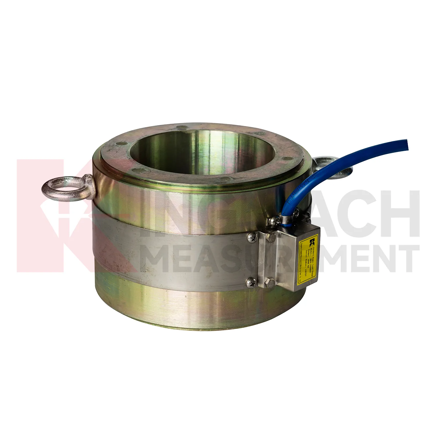
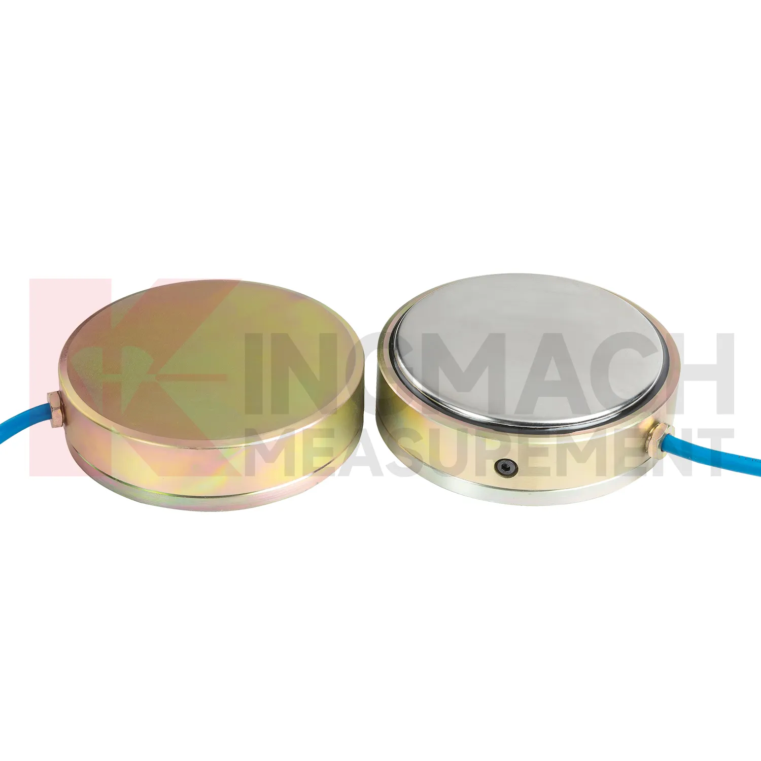
Large Earth Pressure Cell ( VW & Smart Type) JMZX-51XXAT/ ATM
View DetailsFAQ
Start with a simple resistance check using a multimeter. Measure between excitation leads — you should see the input resistance listed on the datasheet (often around 350Ω or 700Ω). The signal leads should show a similar value. A mismatch or open circuit means wrong pairing or a damaged gauge. Then power up and check the signal output at zero load; it should be close to zero millivolts per volt.
A 4-wire load cell has only excitation and signal pairs. A 6-wire adds a sense pair that reads the actual voltage reaching the bridge. This lets the instrument adjust for voltage drop in long cables. For short runs under 10 meters, 4-wire is fine. Beyond that, especially in outdoor monitoring, 6-wire gives you a more stable reading as temperature and cable resistance change.
Drift often comes from moisture ingress, poor connections, or temperature effects. Check the junction box seals first — even tiny amounts of condensation can cause leakage currents. Also verify that the shield is grounded only at one end. If the drift follows a daily temperature cycle, the cable resistance might be changing; a 6-wire connection can help.
Yes, but do it carefully. Use high-quality shielded instrumentation cable, and keep the splice clean and dry. Soldered and heat-shrunk joints work best. After extending, re-calibrate or at least verify the zero and span with a known weight. The longer the run, the more you will appreciate a 6-wire setup.
First, check the excitation voltage at the load cell terminals. If it is missing, trace the wiring back to the indicator or power supply. If excitation is present but no output, temporarily disconnect the signal wires and measure resistance across them at the load cell — a reading close to the rated output impedance means the bridge is intact, and the problem might be a broken conductor or a faulty instrument input.
Share your product type, target capacity, and application requirements. Our team can review the details and recommend a practical next step.
Related Keywords
If you are interested in our products or want to become our partner.
Please leave your contact information, our team will contact you as soon as possible.
Mail: [email protected]
Contact Us: +8613808434127
Address: No. 188 Tongzipo West Rd, Changsha, Hunan, China